Carrier Tstatccprh01-b User Manual
Appliance manuals and free pdf instructions. Find the user manual you need for your home appliance products and more at ManualsOnline.
. Optimum performance is obtained when an outdoor temperature sensor is used with the Thermidistat Control.
Plan installation so that 2 wires can be run from Thermidistat Control to an outdoor location, preferably on the north side of the house or refer to Installation Instructions included with the outdoor temperature sensor for simplified connection. Step 2—Set DIP Switches There is a 4 section DIP switch within the Thermidistat Control which must be properly set by the installer. It is easiest to set these 4 switches before the Thermidistat Control is mounted to the wall, so STOP and complete the following steps: 1. Unlike conventional anticipators, this setting is not determined by current draw. There is no need to measure, know, or compensate for current draw. There is also no droop with this Thermidistat Control. Regardless of setting and number of stages, both heating and cooling will control to their respective set points.
Use up and down buttons to move between F and C on large display. Press SET TIME/TEMP button again to flash upper small display for selection of another option, or press END to exit configuration mode. Option 4—Fan (G) On With W This selection determines whether fan (G) output is to be ON or OFF when any W (furnace or strip heat) output is ON. Option 12—Defrost Heat Select This option allows installer to select the amount of heat provided by Thermidistat Control during a heat pump defrost cycle. This can be very helpful in maintaining a comfortable leaving air tempera- ture during defrost. The Thermidistat Control senses when defrost is in progress by monitoring voltage placed on the O line by the heat pump while defrosting.
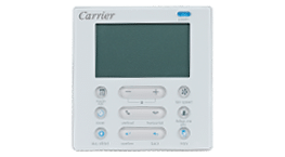
(4 minutes typical, 10 minutes maximum). An additional feature of Thermidistat Control defrost is that it always allows defrost cycle to run to completion. The Thermidistat Control leaves the Y output on as long as outdoor unit holds voltage on the O line, even if it is satisfied. To match these redefined but- tons, a new keypad label, included with the Thermidistat, must be placed over the original keypad label. 2 shows both the original keypad label and the non-programmable keypad label. For further information on temperature selection and program- ming, refer to Homeowner’s Guide.
The various humidity control features of the Thermidistat Control are explained below. They are grouped into 2 sections: humidifi- cation and dehumidification. At the end of each section, instruc- tions on how to select each feature are given. 50 to 90 percent relative humidity. When actual humidity is higher than set point, a dehumidification demand exists. The Thermidistat Control responds by activating its dehu- midify output.

It may also control the compressor and blower, depending on equipment type and dehumidify selection choice. Thermidistat Control and furnace. The relay coil is connected between DHUM output on the Thermidistat Control and COM terminal on the furnace control.
Its normally closed contact is connected between R and DEHUM terminals on the furnace control, where the DEHUM terminal is a spade lug located next to the transformer secondary connections. '-' in place of room temperature Thermidistat Control cannot properly read room temperature. Replace Thermidistat Control. 'E3' or '-' in place of outdoor temperature Thermidistat Control cannot properly read outdoor temperature.
Check outdoor sensor and its wiring. 'E4' or 'E5'.
Manufacturer reserves the right to discontinue, or change at any time, specifications or designs without notice and without incurring obligations. Book 1 PC 101 Catalog No. 03TS-TA17 Tab misc. Thermidistat Model No.

User Manual Introduction
B) Mode Settings Hold (On or Off) Mode (Off, Heat, Cool, Auto, Eheat) Heating Set Point Value.